
Gigabyte GA-P55-UD5 Motherboard
Wednesday, September 23, 2009
Gigabyte GA-P55-UD5 Motherboard

Today, we have a sneak peak at the Gigabyte GA-P55-UD5 revision 0.2 motherboard for the upcoming Intel Core i5 processor series. This LGA1156 motherboard is part of the UD5 motherboard family, which means it features Gigabyte's Ultra Durable 3 technology and the '5' denotes that it should pack a hefty feature set.
Right off the bat you should notice that this board is based off of the LGA 1156 socket for Intel Lynfield CPUs, which has been rumored to be for both Core i5 and Core i7 processors, depending on the CPU features a particular model has. The upcoming Lynnfield processor supports dual channel memory only, so that is why you don't see triple-channel memory support on P55 motherboards like the GA-P55-UD5 shown above.
The Gigabyte GA-P55-UD5 Motherboard features three PCI-Express 2.0 x16 slots. Only the top two are powered by CPU the directly, offering either a single x16 link or two slots with eight lanes each. That means that the bottom slot will feature just four lanes that are channeled to the Intel P55 Express chipset and not directly to the CPU. For those that are worried about multi-GPU support it has been confirmed by Gigabyte that both ATI CrossFire and NVIDIA SLI are supported on the two main physical x16 slots from the CPU. In addition to the PCI-E slots, the GA-P55-UD5 features two PCI slots and two PCI-E x1 slots, although it appears that using a dual-slot graphics card will block the PCI-E x1 slot directly below primary x16 slot. You can also make out the board revision number in the image above, which is 0.2.
The Gigabyte GA-P55-UD5 Motherboard has four dual-channel memory slots that can support up to 16GB of memory at 2000+ MHz/1333 MHz/1066 MHz/800MHz depending on if you are overclocking and what divider is being used. The board's 24-pin ATX power supply header and IDE header can also be seen in the image above.
The rear I/O includes a PS2 keyboard or mouse port, ten USB 2.0 ports, both coaxial and optical S/PDIF out, two powered eSATA ports, two RJ45 sockets for Gigabit Ethernet, 6-pin and 4-pin Firewire sockets and six 3.5mm audio jacks providing the 7.1 channel surround sound as well as microphone and line-inputs.
The Gigabyte GA-P55-UD5 Motherboard has support for four SATA 6Gbps in RAID 0, 1 and six SATA 3Gbps in RAID 0, 1, 5, 10 on the board itself. If that is not enough storage space there are also two more SATA 3Gbps eSATA connectors on the board's I/O backplane and one PATA header on the board itself. That means you can connect 12 SATA devices and 2 IDE devices on the Gigabyte GA-P55-UD5 Motherboard at the same time!

The Gigabyte GA-P55-UD5 Motherboard 12+2 power phases using a standard pair of Power-PAK MOSFETs underneath the two heatsinks along the CPU socket.
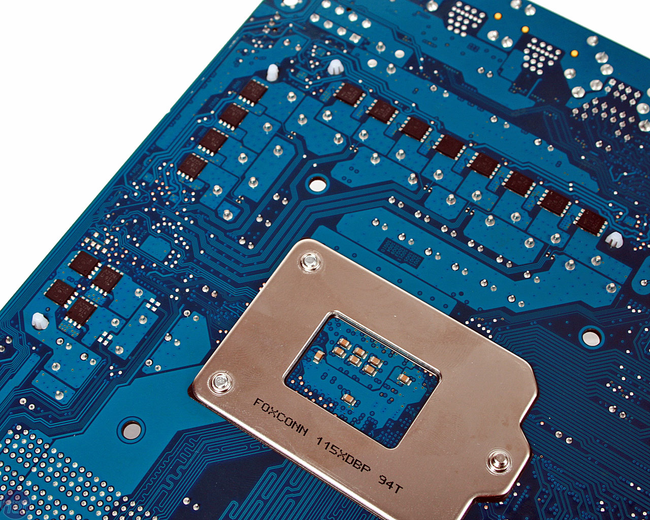
Flipping the board over you can see some more of the components that make up the power phases and you can count them a little easier.
A Closer Look At The Layout
The GA-P55-UD5 mainboard features power, reset and clear CMOS buttons along the bottom right corner of the board. The power button is rather large and easy to identify since it is labeled, but the reset and clear CMOS buttons need some better labeling. It seems the days of having to move a jumper over to clear the CMOS is long gone. The front panel connectors are color coordinated as you can see above, which makes assembling a PC much faster.
Here is a closer look at the 8-pin +12V ATX power connector that resides on the top left corner of the board. Once Gigabyte installs the U-shaped heat pipe to connect all the heatsinks it looks like this will be a tight fit, but still with enough room to be easily functional. You can also see the fan header for System Fan 3. It should be noted that other than the 4-pin CPU cooling fan header the board has five additional fan headers. Out of the six fan headers on the board two are 4-pin headers (CPU Fan and SYS Fan 2).
The P55 chipset heatsink reminds me of a gun metal gray, but I like the look and finish. A PCH fan header is located just out of frame, so adding air cooling is easily possible if you can figure out a way to attach a fan to the interestingly designed heatsink.
The new LGA 1156 socket has a new 'slide' type lever mechanism for opening and removing the CPU, which is new to us. We have not installed and removed the processor enough yet to notice any negatives to the new design.